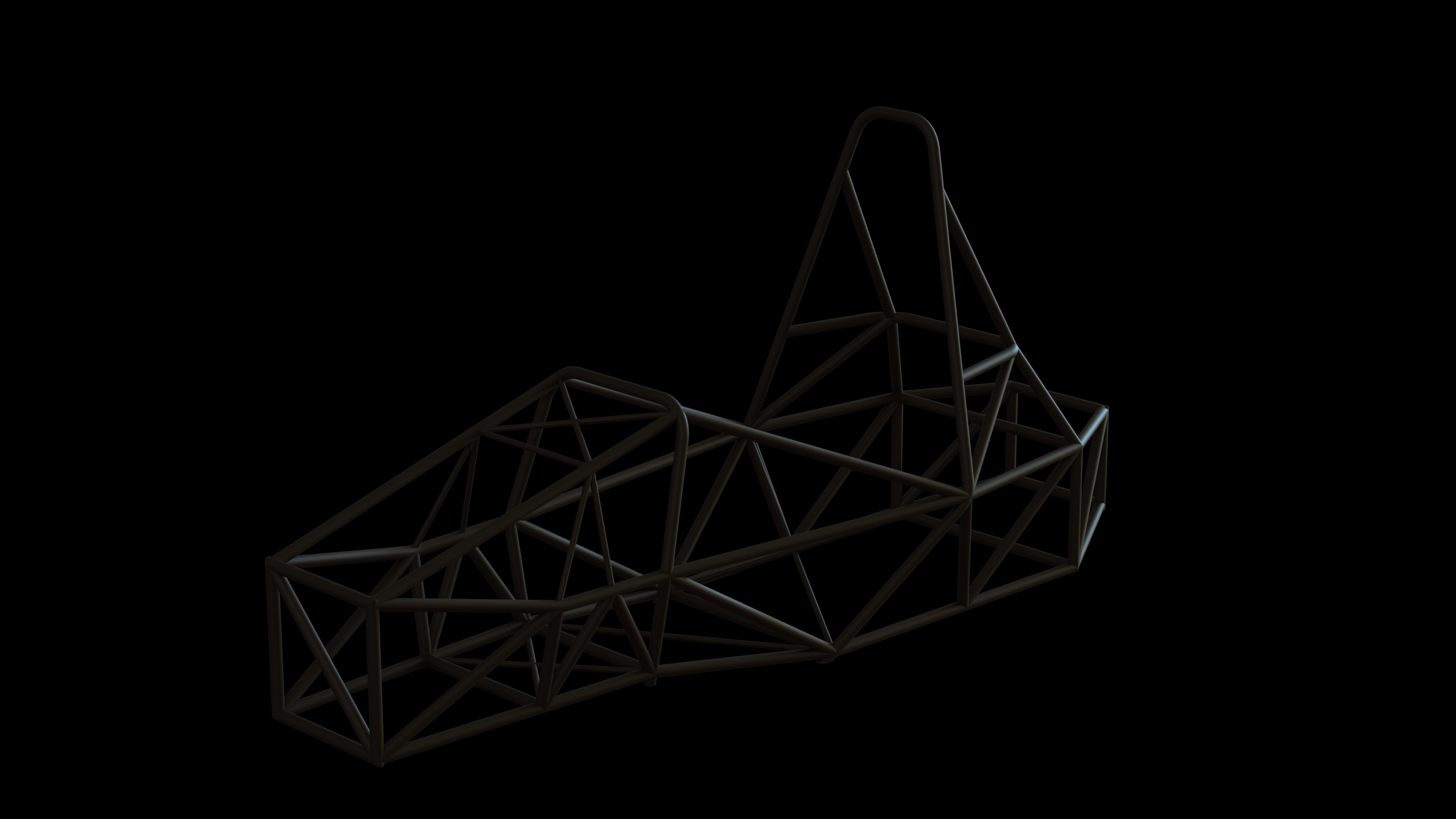
NER25A Chassis
67 lbs. +6 from 24A
1800 Nm/deg Torsional Rigidity, +600 from 24A
Larger driver bay allowing for more effective and precise control
Larger battery packaging for greater power output and ease of maintenance
Narrow nose for aerodynamics packaging space
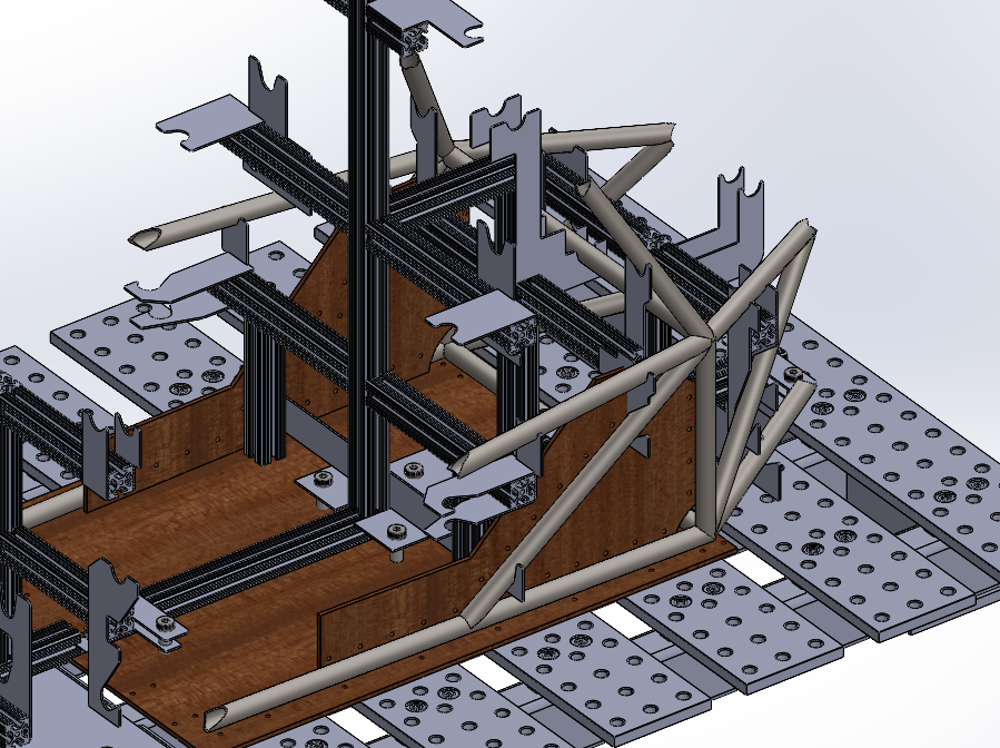
Reconfiguration of front and rear structures to create effective suspension pickup points
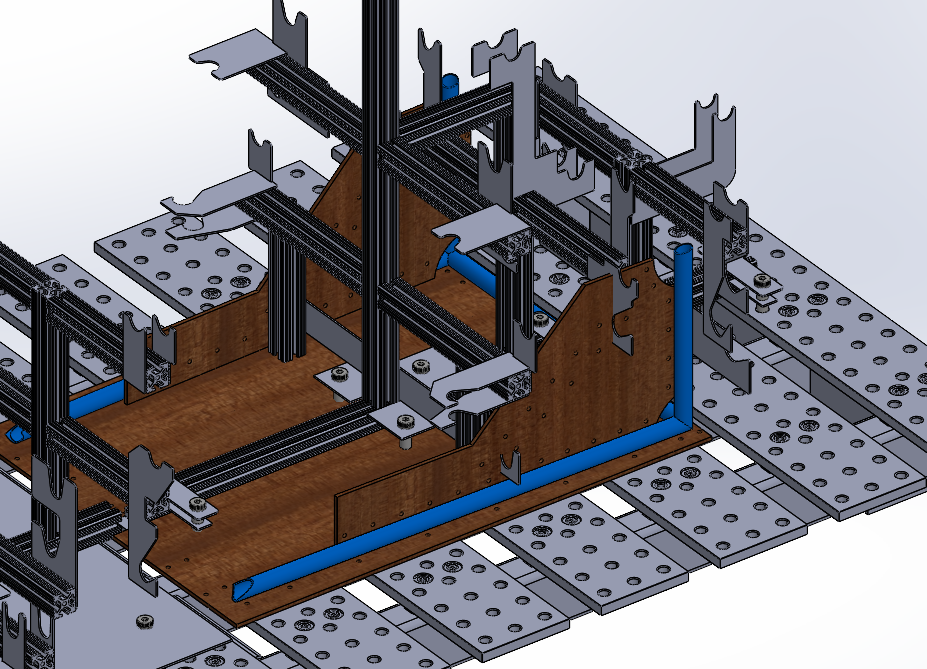
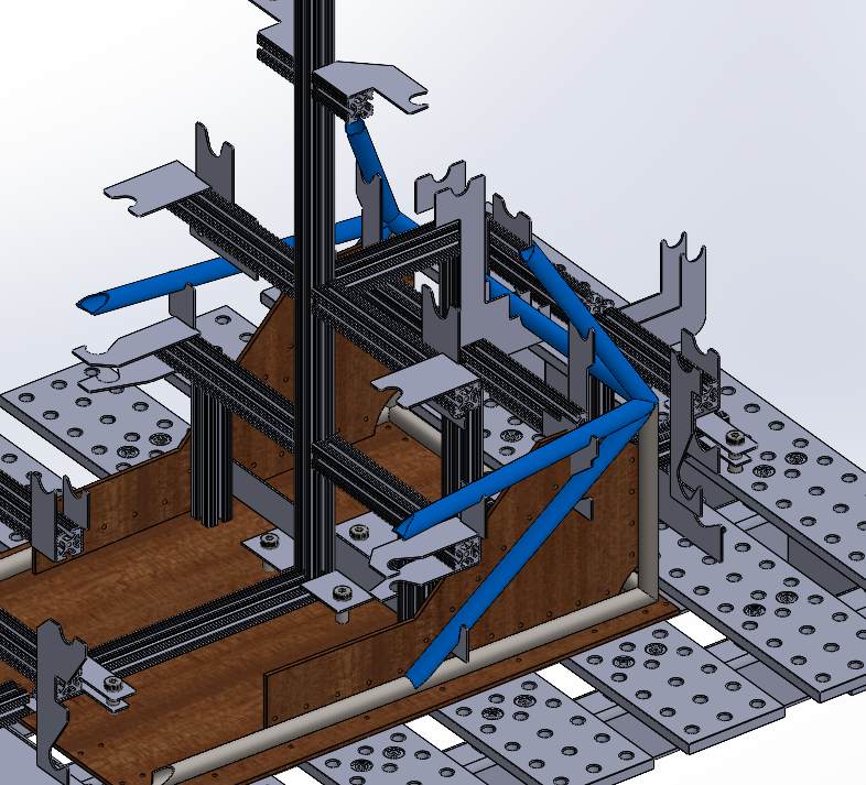
Sub-sized chassis tubes added to increase stiffness in suspension load paths without compromising weight
Objectives
24A was a major pivot from Northeastern Electric Racing’s previous chassis design philosophy. The chassis for our 22 and 17 cars were both overbuilt, each in excess of 100lbs. 24A marked the pursuit of lightweighting at only 61lbs. However, it struggled as a rigid frame.
For formula student teams, handling decides competitions. When a chassis isn’t effectively transferring the load between suspension components across the car, the car’s handling characteristics become sloppy and unpredictable. My primary objective for the 25A chassis was to preserve a light platform while optimizing interactions with the suspension system.
Design and Analysis
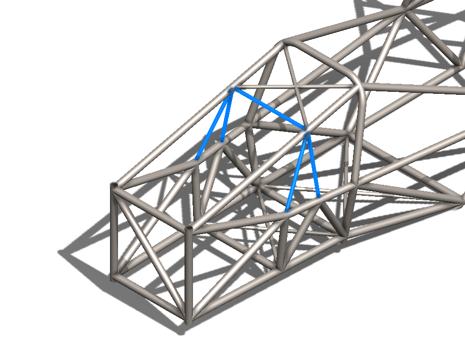
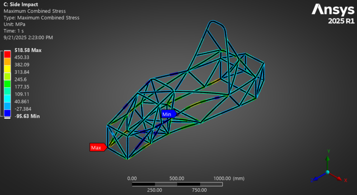
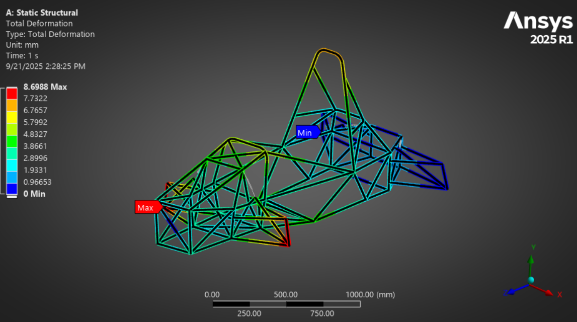
Through iterative simulation and design, I determined that the most effective ways to increase the stiffness of the platform without massively increasing its weight were:
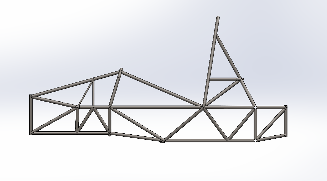
Half-sized tubing in large untriangulated bays in the chassis, particularly between suspension structures, and
reconfiguring the front bulkhead support structure and the rear bulkhead support structure to allow as many suspension components as possible to fall on chassis nodes
Unsurpisingly, the added stiffness also had very positive impacts on the overall safety of the car.
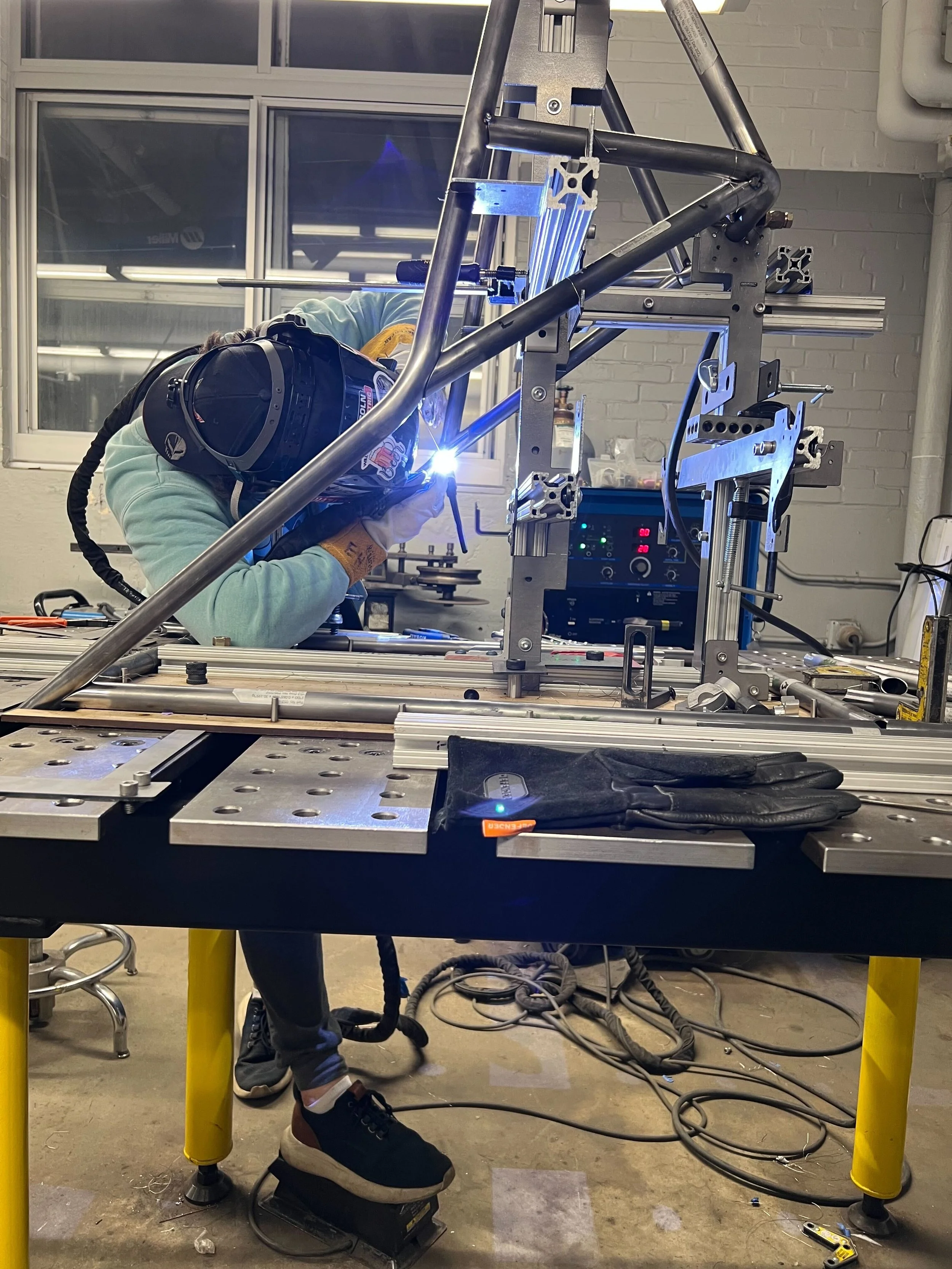
Manufacturing
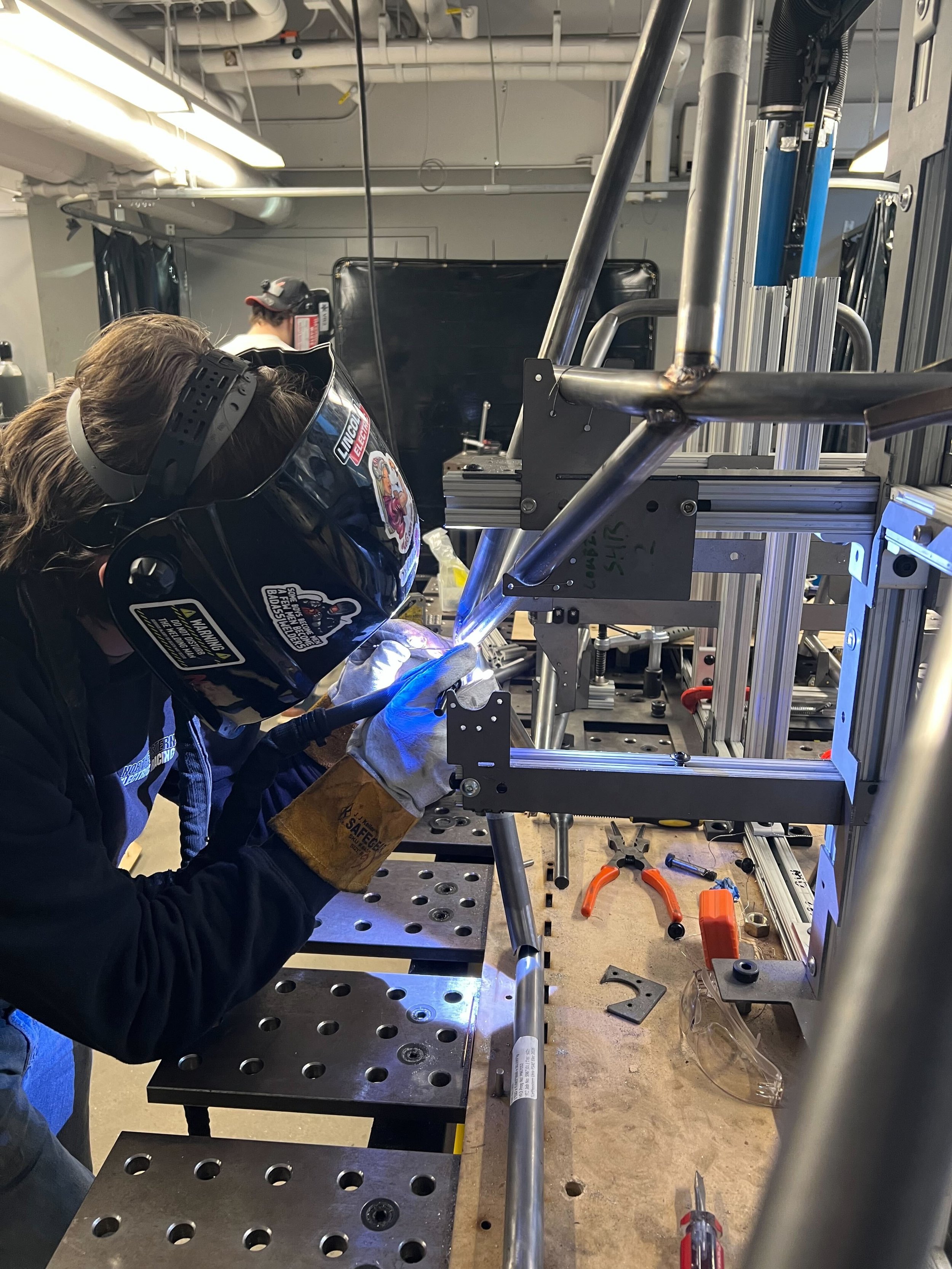
None of the rigorous design and analysis work is meaningful without an effective integration between the suspension system and the chassis in the real world. For this reason, the chassis jigs and suspension jigs were designed off of the same datum, allowing for suspension tabs to avoid any possible chassis tolerance stack-up. The chassis also benefitted from this, because it made it possible to precisely quantify the tolerance and relative position of chassis members to CAD using the jigs, and to correct any inconsistencies. This was in contrast to the 24A jigging assembly, which was self-referential off of the main roll hoop. As a result of the datum, the worst toleranced chassis node for 25A was approximately 0.05in off of CAD, which was an improvement from 24A.
For the manufacturing of the 25A chassis, I had the incredible opportunity to learn to TIG weld through Northeastern Electric Racing. This was very difficult and rigorous because the standards that the team is held to at competitions for chassis welding are very high. I was able to pass a weld test after 6 months of practice, just in time for the arrival of our notched and bent chassis tubes from our CNC manufacturer, VR3 Engineering. This is an achievement which I am very proud of, because historically, chassis leads have not been certified to weld their own spaceframes. However, it was bittersweet, particularly considering the harsh 1 month welding timeline we had to hit among only 4 certified welders.